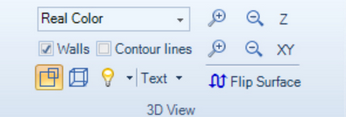
The entire chart can be zoomed using the XY or Z +/- magnifier buttons.
Color scheme
Select an appropriate color. Most often the ‘Real Color’ option will be used as this reproduces the real object most naturally.
If the ‘Zone’ color is used, then the height can be read from the color legend. Each color in the legend corresponds to an input image, also representing the DOF. On the right side of the color legend, a histogram of the height distribution is shown. The white and black triangle can be moved to truncate the colors used in visualization, which can yield better contrast for samples with small height variation.

Color legend
Walls

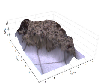
Part of the Berlin Wall – shown with Walls
Contour lines
The ‘Contour’ option will show the image layers.
Projection
Two options exist, perspective or orthogonal view.
Light
Several artificial light models can be applied to change the contrast.
For the ‘Real Color’ view, the ‘None’ option is recommended.
Text
Header and footer texts can be added.
Annotations can be added by right clicking on a position on the 3D surface.
The callout will contain XYZ-information and the text in the ‘Callout Text’ text-box.
By mouse pointing the 3D line chart, the XYZ data is shown.
To add custom text to an annotation box, first select the annotation by clicking it with a mouse button. When selected, the color will change. Then type the text in the textbox.
Flip Surface
This option inverts the surface, like it is seen from below.
Also, useful if e.g. the 3D surface Z-stack was acquired in the wrong direction.

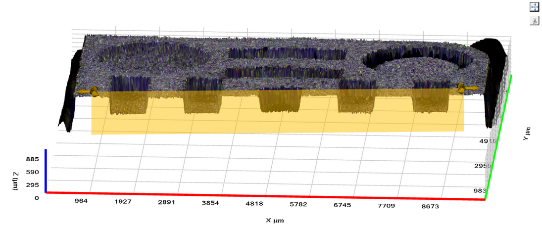
In the upper right corner of the 3D topography view there are buttons to reset the 3D view and cutting the topography to the active 2D profile
Reset View
Clicking the reset view button will reset the 3D scene to the default view.
Cut plane
When a 2D measurement is active, the Cut button can be used to cut away a part of the topography that lies on one side of the 2D profile plane. Using this option is can be easier to see where the 2D measurements are placed in the 3D topography, and it can give a visual view of the cross section between the surface and the plane.
