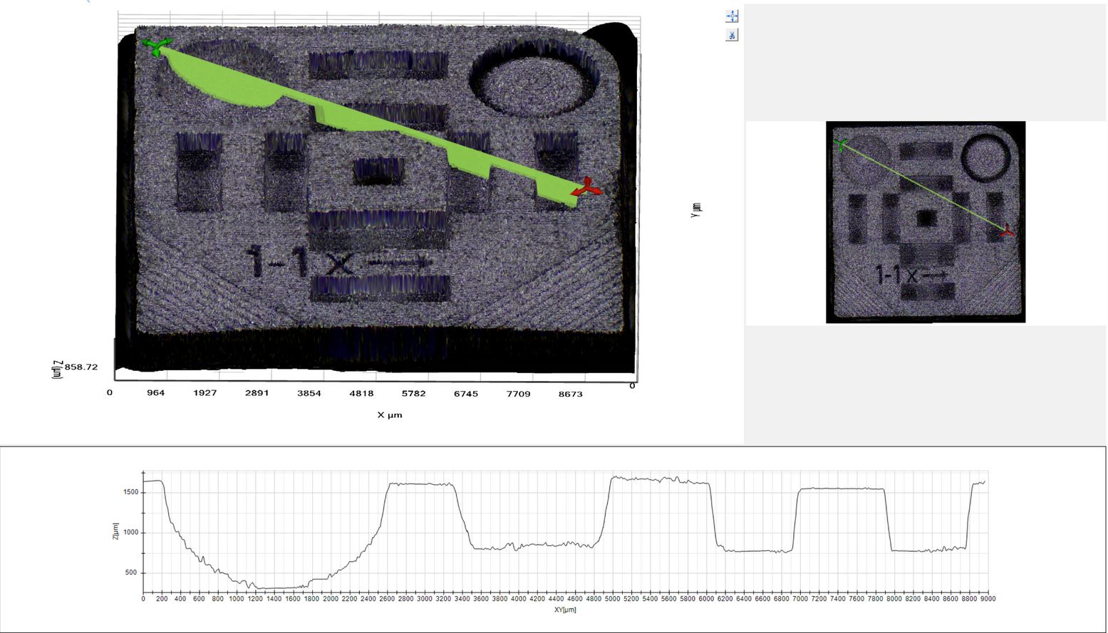
DeltaPix InSight can create 3D surface from a Z-stack of images.
High-precision topography measurement using focus techniques can be realized provided that the in-focus plane of an imaging system is very accurately determined.
To create surface charts, it is highly recommended to use medium resolution images, ~8 MP images are sufficient. More pixels will slow down the processing, and potentially limit the number of images in the Z-stack
i |
The topography processing and display requires a powerful computer to ensure fast creation of images and smooth display. |
Precision of the topography
Precision can be better than 1 micron, dependent on optics magnification, focus motor precision and light quality. Several factors influence the precision:
1.A low depth-of-focus (DOF) is desirable. High magnification and numerical aperture generally decrease the DOF.
2.The number of focus slices acquired for processing. If many slices are used the better precision. As a rule of thumb, the slice distance should be less than the DOF, around 1/2 DOF to 1/4 DOF is recommended.
3.The best Z resolution is 1/250 of the Z used travel range, so if the difference between top and bottom level is 1mm, then the very best precision is 1000um/250 = 4um.
4.The precision is also limited by the number of Z-stack images used. As worst-case example, if only 3 images are used, and the difference between top and bottom level is 1mm, then the precision is 1000um/3 = 333um. The result may look better since a configurable interpolation and noise reduction between the Z-stack layers is done.
5.The surface of the object. Shiny or black surfaces generally are difficult to handle.
6.The precision of the mechanics – primarily the focus motor. This is however normally in the um-range.
Topography view
When a topography is loaded or captured, it will appear in a 3-split view where the 3D image is visualized on the upper left, the 2D view on the upper right, and any active profile on the bottom. Changes done in the 3D view is immediately shown in the 2D view and in the profile. The 2D window can not be manipulated, but the both the 3D view and the profile view can be zoomed by using the mouse wheel and panned by using dragging the mouse with the middle button pressed. The 3D view can be rotated by dragging the mouse with the right button pressed.

Main topography view